The La Jollita was a first of it kind. It's a
"Rare large scale Pylon Racer for the Miniature Goodyear Event or sport
flying". Miniature pylon racing was all the rage in the late 1960's - early 1970's; they were designed to be powered by a potent 40 size glow engine such as the OS MAX H 40 P. Other contemporary kit manufactures produced kits for this class, such as Goldberg's "Shoestring" Sig's "Minnow" and Great Plane's "Cosmic Wind. But the least popular and I never knew why, was the William's " La Jollita". These were truly 1/4 scale model airplanes that fact is hard to believe, when one considers that the wing spans were only 40 odd inches. The full scale airplanes themselves were very small; they were hardly bigger than what today we call Giant Scale models.
Full scale Rivets Midget Racer
The kit Contains select balsa and plywood, 29 hi-impact plastic
parts: cheek cowls; wheel pants; all wing ribs; wing tips and turtle back. Also included is a preformed aluminium landing
gear, all hardware, clear scale canopy, pilot figure and more. As I recall after all these years, it was a very high quality kit and an easy build.
The sun came out here yesterday afternoon and I took the opportunity to go to the field with some of my electric planes;I flew the Beaver, Lightening and a Williams Brothers' Pylon racer that I made when I was 31 years old (46 years ago), while living in St. Louis, when I worked with McDonnell Aircraft. I kept it all those years and recently restored and converted it from glow to electric power witch in itself was no easy matter. You can't imagine what a thrill it was for me to see her perform yesterday, ripping around the field doing those bank and yank Pylon turns for 5 minutes plus. The perfect roll on landing to finish off the flight was particularly satisfying. I hope that she will survive a little while longer, so I can get more experience flying her. The next time I will try to have a flash card in my GoPro so that I will have a record to remind me of the experience.
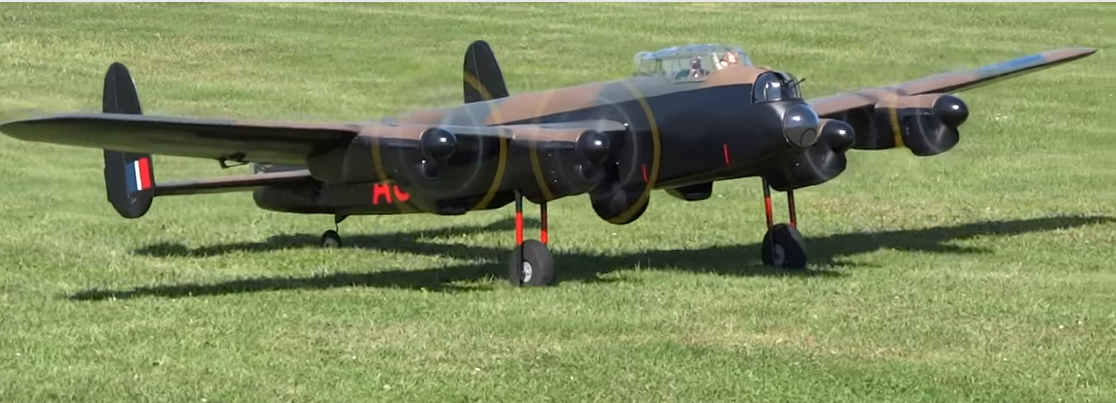
The 134” Lancaster is a scaled up version of the 72” version and incorporates the exact same build techniques as its’ smaller sister. So for building information please refer to the72” Lancaster pdf down load.
Originally designed for 4 speed 600 motors with gearboxes, back in 2002, model will now benefit greatly from Brushless and Lipo batteries.
For IC conversion, 4 x .40 size 2-stroke or .52-4 stroke engines will provide adequate power.
The model is design for retractable undercarriage.
Plan, canopy, cowls and turrets, are available as is a CNC pack and wood pack.
The CNC pack includes, ply fuselage formers, ply wing & tailplane ribs, nacelle structure and spar braces.
Each motor has its own battery, electronic speed control, receiver and receiver battery. The red wire from the ESC is pinned back and only the signal wire and the black wire leads to the receiver's throttle channel plug.
The wing's spars are bolted to the fuselage's frames by 2 1/4 inch bolts which engage blind nuts in the frames; making a very tight joint at the aircraft's centerline.
The main landing gears are purchased from the designer's store.
The gear is pneumatically actuated.
The multiple receivers and batteries give the plane several layers of redundancy.
Most of the forward area lacks detailing which will be added after she becomes a seasoned reliable flyer.
All the glazing and finishing items are available separately from the kit manufacturer.
Gradually it evolved into a seasoned reliable flyer and with additional detail ling completed it evolves into a model of the famous Dambuster Lancs of WW2
.
Published on 6 Sep 2017
134 inch wing span, Lancaster Bomber. Each engine nacelle is fitted with its own radio receiver, battery, electronic speed controller and brush-less motor.
XFLR5 is an analysis tool for airfoils, wings and planes operating at low Reynolds Numbers. It includes:
XFoil's Direct and Inverse analysis capabilities
Wing design and analysis capabilities based on the Lifting Line Theory, on the Vortex Lattice Method, and on a 3D Panel Method
This tool was used to predict the aerodynamic characteristics of a flying wing
glider and determine the power required for safe takeoffs and good climb rates.
Future Flight Kit
The bell cranks were removed and micro servos mounted at their locations.
Control is provided by two 90 micro servos one attached to each of the wing panels control surfaces. The hook-up wires are routed through the outer Ny-rod tubes which were already in place from the old control arrangement.
This aircraft has been flown successfully in the past as a high-start glider and as a geared brush motor powered glider. Pitch and roll control was accomplished by two standard size servos mounted to a mechanical mixing mechanism which was located in the central compartment with the deflections imparted to the control surfaces by ny-rods and bell cranks.The demise of the wing come when one of the bridle rings slipped off during a hi-start launch. Like most of my flying mishaps the damage was not total and the wing was repaired slowly over the next 20 years or so and now we are at that point where a new experiment is taking shape with a few structural improvements and thanks to a new Spektrum dxi 6 transmitter it will use electronic mixing. For power we intend to use a 70 mm EDF or two 55 mm and of course 2500 mah Li-Po batteries.
The earlier flights were conducted with and without the tip fins and as far as we could tell the fins had no noticeable affect on the craft's stability.
Stability Analysis:
The Fins and Stabilizers were removed from the model to see if the model exhibited any stable flight characteristics. To compensate for the lack of a stabilizer the trailing edge flaps were deflected upwards 5 degrees inboard tapering to 3.5 degrees at the wing tip. These flap angles were a guess based on memory of the values required to trim the wing on those earlier flights.
For initial displacements in the longitudinal and lateral axis the model returns to its normal attitude in a few cycles and the osculations are quickly damped out. This is particularly true for the pitch direction.
We thought we would investigate what would happen to the lateral stability if we were to add tip fins to the model. Check out the mode one lateral stability animation.
Stability Vs C of G Location:
The effect of C of G location on the stability of the model was investigated by varying the location and re-running the analysis to attempt to establish a stable condition. The model could not be trimmed until the position was moved to 12 inches behind the reference plane. At that point the the results of the analysis predicted a Velocity Never to Exceed (VNE) of 97 mph. The optimum position was established at 12.5 inches with a VNE value of about 130 mph.
The next plans involve adapting the wing to electric duct ed fan power installation.
I was inspired by this fantastic jet powered wing model.
The original of the plane that inspired this design was never flown. It hangs on the wall of a hangar in the Chino airport in the USA. The original was designed with pusher prop but was intended to have a turbine eventually. It was built in the 1980's and was modelled on the Horten principles. Note no fin and no rudder at all.The plane is scratch built by John Wright from a design by a German modeller Andres Chavarria.The plane has 2m wingspan and weighs 5 Kg
The engine is a 60mm diameter turbine that John Wright has designed and made. It is known as the Sprite. It weighs 440 gm and runs at 250,000 rpm
Thrust is 3.25 Kg. This is not a commercial project.
The design proved to be very strong and very manoeuvrable and has had many flights. Despite the lack of rudders and fin is fully aerobatic.
Model was purchased several years ago without any radio or electronic components.
It was designed to be powered by a pair of GWS geared brush type power units and it was first flown successfully a few times using this power set-up. But we were never completely satisfied with its performance and we spent a lot of time trying to figure out how to attach those beautiful spinners
to the propeller shafts .
Now it's fitted with a pair of matched brush-less motors turning 5X7 GWS propellers. But still no way to mount those spinners. I never understand how they rate these motors but, I would estimate each is equivalent to a good 049. Now at the speed these props turn it is impractical to mount large spinners. The Project to make this model into a reliable fun to fly model airplane has been an off-and-on effort for about five years. The first problem to solve was the nosing over and digging in on takeoff caused by the very small fixed nose wheel ( we always fly from grass so this is a big problem). Problem solved by making a stout oversize steerable nose wheel which doesn't look that pretty, but from 20 feet it is not that distracting and the smooth straight takeoff runs go a long way in compensating for the looks of the thing.
There is no rudder control but the rudder channel is used for the steerable nose wheel and the elevator is activated by push pull wires which makes for a simple system.
Lots of room inside the radio compartment for a much larger battery then the 1800 mah 3 cell one used for the initial flight. Cooling air for this compartment is directed through the gun ports in the nose (drilled oversize) and exited through the opening at the back of the canopy. Since my Spektrum mini receiver was being used at the time in another project, we used an old GWS 4 channel park-flyer 72 mhz one for these flights.
ESC's are attached to the wing with Velcro or as the people at the dollar store call it 'hook and loop".
Under the wings we have mounted a pair of 30 amp brush-less motor controls. The key thing here that is essential to follow is; only one is used to power the control system. This is accomplished by removing the pin for the positive (red wire) and pinning it back out of the way. I tried more times than I care to remember to get both engines running at the same time, without success. I even tried two stand alone battery ESC combinations; It wasn't until I cut the red wire on one ESC was I able to get each engine turning simultaneously. Even now they each stop and start at different throttle setting which makes for lots of excitement on landing.
There is not enough room inside the fuselage for the two ESC's so I opted for mounting outside under the wings where cooling is not a problem. I used a 1800 mah 3 cell battery for the flight shown below but now I have room for a much larger battery in future flights.
As you probably noticed from the video, I need to give some thought into what landing techniques should be used in landing this model. This is because the two motors quit at different low throttle settings (equal thrust at full to about 1/3 throttle) the plane yaws to the dead engine. This situation has to be avoided so, I have to train myself to snap the throttle closed while over the field at half throttle; something to work on the next visit to the field.