Many years ago I purchased the collection of a deceased local modeler and among the many items included in the lot, was a partially completed Pica kit of the Waco YMF 3 biplane.


The plan calls for a single aileron servo to be mounted at the wing centreline moving the ailerons through a wire and bell crank system but we elected to actuate the ailerons with dual servos mounted at the control horne wing station.


 Nylon hinge tange is used to attach the ailerons to the wing structure. I am skeptical about the integrity of this form of hinging but because there are three hinge points there will be a certain degree of redundancy if one fails.


 Drilling holes for wing attachment is a job that I absolutely detest since there is just one chance to get it right. The wing and the fuselage have to be held in as near perfect alignment while drilling pilot holes for hold down bolts and front dowl. The care taken with this process seems to have paid off in this case; with the components attached in place, wing alignment is well within eye pleasing tolerances.


Fuselage Plan Sheet 1
Wing Plan Sheet 2
I have always admired the Waco line of biplanes although I admit that my knowledge of the various models in the Waco line-up was very limited to say the least. The Pica manufacturer describes the kit as a semi-scale 1/6 size of the Waco YMF-3.


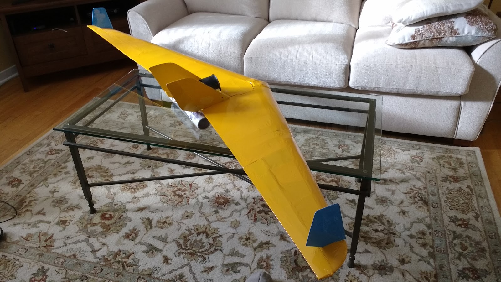
It will be a long time before our Waco will be looking anything like the above.


My Webra 61 Speed fits perfectly in the wooden engine mount.


The plan calls for a single aileron servo to be mounted at the wing centreline moving the ailerons through a wire and bell crank system but we elected to actuate the ailerons with dual servos mounted at the control horne wing station.

The attachment of the interplane struts to the upper and lower wing panels is detailed above and below.

We elected to set up the ailerons with a servo mounted in each lower wing panel and located at approximately the control horn station. Since the wing section is not very deep we looked for the smallest pair of servo that we had, these happened to be a pair of never used Airtronic servos. To use these servos on our Spektrun radio system the pinout had to be modified to be compatible with Futaba connectors.


This process involved identifying the three output airtronic wires and re-attaching them to the appropriate location on the Futaba connector.
Through trial and error we discovered that the Airtronics lead with the white line is actually the positive. From there it was straight forward; the other end lead had to be the signal and the center lead is the negative.


Sheeting will be required around the servo cutouts to provide a surface to stick the covering material to.

Lower wing nearing completion.


Hinging and mounting Tail Feathers
The Pica plans are not too clear on the details of the relationship between the vertical fin and the horizontal tail plane so we went to AeroFred.com and downloaded their Waco F-3 plan which is clearer on the positioning of the tail components.

Hinging and fitting Tail Feathers

The spars in the tail surfaces are made from spruce which is hard to slot so, we decided to use Robart Steel Point Hinge Points (#308). These hinges require drilled holes for insertion into the structure. The only time consuming procedure was the forming of the square recess required to bury the clevises which is essential for a minimum surface gap. The original Gorilla glue proved ideal for attaching the hinge points to the structure because if its gap filling qualities. Care not to use it too liberally proved a wise move. Soaking the moving clevises in baby oil to negate the chances of any excess glue inhibiting movement was also a good idea because, this very thing occurred with one of the hinges and the glue was easily removed because of the presence of the oil.
The hardest thing to date was adjusting and fitting the inter plane struts; each strut is attached at four separate points.


Covering
Sig Koverall was selected to cover this air-frame in an effort to control the cost.
Koverall is a cloth covering of the type used on full-scale aircraft, but in a lighter weight (1-1/4 oz. per sq. yd.) for models. Koverall can be used on almost all R/C models large or small. Its superior strength and low price has made Koverall a real favorite with builders of giant size models. It's the most economical cloth covering you can buy!
SIG Koverall is an uncoated, heat shrinkable plain fabric. It has no glue on it. To adhere Koverall to a model, you can either dope it on ala the traditional silk-and-dope method, or better yet, use SIG Stix-It heat activated covering adhesive (see below). Just brush a coat of Stix-It on the model framework, let it dry, then iron-on the Koverall just like you would a much more expensive iron-on fabric covering. Once the Koverall is stuck down around the edges, it can be shrunk perfectly tight with an iron or heat gun. Seal the Koverall with 1 - 2 coats of Sig Nitrate Clear Dope and then apply the finish of your choice.